The History and Future of Custom Valve Concepts
We began our journey in 1942, producing leather tooling and other products for manufacturing. When the market evolved, so did W.A. Kates Company. Today, Custom Valve Concepts still produces the quality Kates Valves, researched and developed, and manufactured in-house. With some products still in use after 50 years, we’re proud of our work and our service to customers.
Before Custom Valve Concepts, there was Atom Tool and Die Company, dedicated to manufacturing tooling for leather material. Atom was founded in 1942 by Willard A. Kates and 3 of his business partners. The first manufacturing facility was located in Chicago, Illinois and was the basis for what later would become Custom Valve Concepts.

Atom Die and Tool Engineering, 1948
L to R: Buddy Click, L. A. Grzenia, A.C. Bennett
W.E. Schwartz, W.A. Kates, John Kleingberg
In 1948, when a shift within the industry meant the demand for leather tooling began to decrease, Kates and the Company set out to find a new direction, a new industry in which to continue creating quality products. Research and development commenced within the company’s machine shop for new technology, launching the discovery of new and viable and valuable products that set the course for the future of the company. In 1949, Kates became the sole owner of the company and in order to ensure the company’s stability, he began to make changes within the company.
As the discovery of and then the first design of the new Kates Flow Rate Controller was built, the company’s name was changed to W. A. Kates Company. In 1960, under Mr. Kates, W. A. Kates Co. facility was moved from Chicago, IL to Deerfield, IL.
New Ownership
After almost 40 years of leading and setting the foundation of the company, Mr. Kates sold W. A. Kates Co. to Frank A. Taube II, in 1984. Taube eventually relocated the company to Madison Heights, Michigan in 1988, where it’s located today. And in 1995, John Taube took over the company as the President.
Custom Valve Concepts
In 2005, the company’s name was changed to Custom Valve Concepts as Susan and John Taube took ownership and became President & CEO and Vice-President, respectively. The Kates Flow Control Valve remains the core product as others have been introduced via research and development internally.
Under their direction, Custom Valve Concepts has continued to provide quality service to all as stated in the company’s motto: “To serve our customers as we desire our suppliers to serve us.”


Susan Taube John Taube
President & CEO Vice - President
Technology
Evolution of Kates Fluid Flow Regulating technology
As W.A. Kates transitioned into the flow control industry in 1949, the development of their designs continued to progress as time went on. These models have always been designed as fully mechanical flow control devices. The original Kates Rate Controller technology was designed to control flow through cylindrical weight geometry. This design was constructed in 1949. A weight operating technology for a Fluid Flow Regulator was patented July 30, 1957.
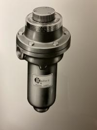
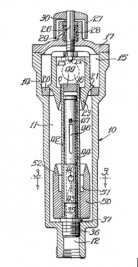
Image of a W. A. Kates Fluid Flow (weight) Regulator (left)
Schematic of a W. A. Kates Fluid Flow weight (50) (right)
This innovative design feat inspired a new valve technology. The blueprints above show in fig. 21, the valve itself while the inlet opening (fig. 12), and the outlet opening is shown as a dotted circle within the valve (fig. 21) chamber (fig. 16).
How Kates worked
The cylindrical weight geometry (fig. 50) was affixed or bonded to the sleeve (fig. 42). As augmented fluid flow or pressure differential occurred at Orifice, the sleeve and weight joint would shift in the upward position affecting the opening of the inlet valve ports (fig. 40, 41), reducing the fluid flow and allowing the pressure differential to decrease. As the flow comes to an equilibrium, the position of the sleeve/weight joint and inlet port openings would then return to the position shown in the upper right schematic.
In 1956, the flow regulating technology was revised to control flow through a spring mechanism. An adjustable orifice technology within a pressure differential responsive system was patented on August 13, 1963. An example of this technology is shown in the figures below.
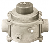
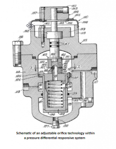
Image of a W. A. Kates Adjustable orifice technology (left)
Schematic of an adjustable orifice technology within for a pressure differential responsive system a pressure differential responsive system (right)
The Adjustable Orifice technology was introduced to create an orifice with an adjustable area for higher accuracy. The Adjusted Orifice assembly (fig. 122) is a manually operated mechanism. The pressure differential is provided between the inlet (fig. 117) and outlet (fig. 119) openings by means of the adjustable orifice and flow regulating valve (fig. 123).
In 1963, the model was revised to a more complex internal flow-controlled system introducing the Internal Differential Pressure Regulating Valve (IDRV) technology developed in-house at Custom Valve Concepts. The IDRV moves freely (& vertically) within the valve and is attached to a coil spring.
As shown in the figure below, there are three operating pressures. P1 (Red region) is identified as the inlet or upstream pressure, P2 (Blue region) is identified as the internal pressure and P3 (Green region) is identified as the outlet or downstream pressure.
Changes within the upstream pressure directly affect the internal pressure, causing it to adjust to the changes in flow. Changes within the downstream pressure, directly affects the positioning of the IDRV and the area of the exit valve ports in order to adjust to the changes in flow.
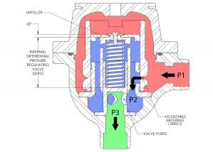
Image of the Internal Differential Pressure Regulating
Valve (IDRV) technology within a Kates valve
To maintain constant pressure across the Impeller and Adjustable Metering Orifice, the internal pressure, must also remain in equilibrium. If P2 is too low, the IDRV moves down to decrease the area at the exit ports resulting in an increase of internal pressure. If P2 is too high, the IDRV moves up to increase the area of flow at the exit ports. This, in turn, will decrease the pressure, creating equilibrium across the system.
Learn more about the functionality of the IDRV, within the Kates Valve, here.
How Processes have Developed
The Research & Development (R&D) processes at CVC have become more efficient and innovative over the years. From their engineering to manufacturing processes, CVC has created systems that mitigate R&D steps while efficiently assessing the products and tooling at which they produce or use.
The changes that have been made to the engineering process have improved the ability to determine the functionality and actions of products via Finite Element Analysis (FEA) methodologies. CVC then utilizes real-world field data from customers to simulate and evaluate responses to the applicable loading and stresses. The utilization of this FEA application and optimization process creates a system of Analysis Led Design of a product which helps reduce the testing and prototyping R&D steps of design optimization.
The manufacturing process has also been modified to create a more efficient manufacturing process via Computer Aided Manufacturing (CAM).
For example, Kinematic responses within a system can be generated to determine close to accurate assumptions of machinery interaction through the duration of the machining operation. These simulations allow for manufacturing engineers to determine how the system will operate in terms of tooling clearances, feed and speed parameters, and any other potential collisions or mishaps. With this method in place, manufacturing engineers can begin machining with an assumption that operating parameters are known. This helps CVC test the Kates valves for uses throughout multiple industries, such as oil and gas, power, chemical, water, and even food production, more efficiently and accurately.
With these processes and technologies in place, CVC has been able to streamline Lifecycle Management to produce a more effective engineering and manufacturing process.
Our commitment to our customers is to continue providing support for our products for a lifetime. As such, these methods are not only utilized for new designs but also for legacy models with an objective to improve the design and life of the product. For example, an existing valve technology used within the fracking industry was revised via their new R&D streamlined design, manufacture and testing process. With parameter changes sent from the customer, the objective was to meet the customer’s new requirements but also increase the longevity of its preceding design. The valve was successfully evaluated and testing within six weeks, decreasing the R&D process by a great margin. Rather small, medium or large-scale projects, CVC’s prototyping capabilities allow them to provide quicker and more efficient product results.
With the continual improvement of processes through technology innovation and training, CVC will continue on with its 70-year tradition of product innovation and expanding markets.
###
Custom Valve Concepts is an Engineering and High Precision Manufacturing company specializing in the design and manufacture of high quality and performance flow control technology, for a wide range of applications. CVC’s product line, whether the Kates Flow Control Valve or custom designed valves and other flow control products, has been utilized in every major industry.
With their products and services ranging amongst a wide variety of applications and capabilities, CVC prides itself on putting people first and providing superior engineering and manufacturing services within the development of their products.
Custom Valve Concepts is located in Madison Heights, Michigan.
Learn more about Custom Valve Concepts and their wide range of products and services.


Sign up to receive the CVC Engineering Insights in Your Inbox:
Join us on Social Media!


Learn more about Custom Valve Concepts
Blog categories
- mechanical design (7)
- General (15)
- history (1)
- quality (4)
- manufacturing (4)
- meet the team (4)
- FAQ Kates (3)