What is an Automatic Flow Rate Controller and How Does it Work?
Custom Valve Concepts have been manufacturing flow rate controllers for every type of application from simple blending to high-pressure hydrogen gas for hydrocrackers for decades. Used worldwide in a variety of applications across multiple process industries such as wastewater, power, chemical, gas, and oil, and military for a variety of applications, Custom Valve Concepts flow control valves regulate the flow of a liquid.
While regulating the flow of liquids may seem to be a fairly straightforward concept, the advantage of Custom Valve Concepts Flow Control Valves, when paired with Kates Automatic Flow Rate Controllers is the ability to automatically regulate flow regardless of pressure fluctuations. That ability to regulate the flow regardless of pressure fluctuations results in reduced waste in every step of the flow process, decreased maintenance and repair costs, and better utilization of both time and money, all contributing to your organization's bottom line.
How Do Flow Rate Controllers Work?
Flow rate control is typically accomplished by multiple components in a process system. Flow control may be necessary for a wide variety of reasons such as; controlling temperature in a process vessel to optimize a chemical reaction or to maintain a fluid viscosity; controlling mix ratios in a batching or blending process; minimizing product usage by limiting flow; dispensing accurate volumes for a variety of applications from beverage blending to custody transfer. Flow control utilizes several distinct products to work together to maintain the desired flow rate.
Three distinct components are typically used to accomplish flow control; a flow measurement device, a flow adjustment device, and a computation device that is adapted for the application and can receive input from the metering device and compare it to a set signal relaying an appropriate signal to the flow adjustment device. These three products are generally an in-line orifice plate with a differential pressure transmitter or a flow meter, a control valve (either electronic or pneumatic actuated), and a programmable logic controller (PLC.)
Components Purpose and Principle of Operation
The first component is the flow control valve, which is used to regulate the flow of a fluid. A pneumatic or electronic signal will typically be used to position the valve opening; in certain applications, hydraulic actuators may be also used. The valve itself is a passive device that requires actuation and a positioner to be incorporated into a flow control loop. The signal generated by independent devices such as flow meters or temperature sensors is sent to a control device which in turn modifies the output signal to direct the action of the control valve. The control valve then restricts or increases the opening of the flow path in a system as needed A wide variety of control valves can be used and are selected based on the type of fluid to be controlled and other variables such as temperature and pressure. Ball valves, needle valves, plug valves are examples of the type of valve choices that can be selected based on your specific application and requirements.
The Programmed Logic Controller or PLC can be either a single control design loop or part of a much larger distributed control system. The PLC may be connected to a computer through standard USB, Ethernet, RS-232, RS-485, or RS-422 cabling. Under IEC 81131-3, PLCs can be programmed using standards-based programming languages; the most commonly used programming language being Ladder Diagram (LD) also known as Ladder Logic. Common control signals are 4-20ma, 1-5vdc, and 3-15psi; the PLC modifies and relays a proportional control signal from the metering device to the restrictive device to alter the flow.
The next factor is flow metering itself. Flow metering can be accomplished with many different devices, the most common and simplest of which is using a differential pressure transmitter across a traditional orifice which can vary from a fixed drill hole to a calibrated needle valve which acts as a fixed restriction. Magnetic flow meters, ultrasonic flow meters, and vortex flowmeters are also used to measure flow.
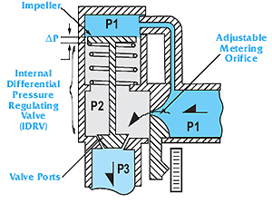
Moving from the multiple unit flow control loop is the simpler and smaller profile Kates Automatic Flow Rate Controller. It’s self-contained unit does not require an external power source to operate. The internal regulating valve and adjustable orifice within the unit are immersed in the fluid, allowing for rapid response to pressure fluctuations while only requiring a ten-pound pressure drop to operate. The design advantage also yields set point accuracy across a greater turndown ratio of maximum to minimum flow when compared to a control valve. Longer operation and maintenance-free service are also results of exceptional design. These devices are used in a wide variety of industries including gas and oil, power, chemical, wastewater, and military.
Put Flow Control Values to Work for Your Process
Process plants consist of hundreds, even thousands of control loops all networked together to produce a product. Each of these control loops is designed to keep some important process variables, such as pressure, flow, level, or temperature within a required operating range to ensure the quality of the end product. Each loop receives and internally creates disturbances that detrimentally affect the process variable. In addition, interactions from other loops in the network provide disturbances that influence the process variable.
To reduce the effect of these load disturbances, sensors and transmitters collect information about the process variable and its relationship to the desired set point. A controller then processes this information and decides what must be done to get the process variable back to where it should be after a load disturbance occurs. When all the measuring, comparing, and calculating are done, some type of final control element must implement the strategy selected by the controller. The most common final control element in the process control industries is the control valve. The control valve manipulates a flowing fluid, such as gas, steam, water, or chemical compounds, to compensate for the load disturbance and keep the regulated process variable as close as possible to the desired set point.
The benefit of a self-contained flow controller is its compact profile when compared to the plumbing and electrical requirements of a multiple device alternative. The ability of a Kates Flow Controller to self-adjust to pressure changes, which are the most common disruptors in a process control system with 1-2 second response time creates simplicity and accuracy when compared to three devices interacting to accomplish the same task. That simplicity and accuracy in turn allow for more efficient and cost-effective operation.
We’re Here to Help You Select the Best Automatic Flow Rate Controller for Your Needs
With so many automatic flow rate controller options and variables, it’s good to know the experts at CVC are here to work with you when it comes to matching components to the application. We offer everything from our successful line of Kates Valve Automatic Flow Rate Controllers and to PVC Automatic Flow Rate Controllers, ideal for working with corrosive mediums, to I/Q Valves to Flo-Miser Flow Rate Controllers which offer immediate response time to pressure variations, eliminating hunting and oscillation. Kates Micro-Flo Needle Valves and Mini-Flo Automatic Flow Rate Controllers round out the CVC Automatic Rate Controller lineup.
We can even assist you in selecting the Programmed Logic Controller to fit your application, the number options and varied price range can overly complicate the process.
To learn more about the latest Custom Valve Concepts product development, emerging technology, new applications, and engineering insights, subscribe to our blog.

Sign up to receive the CVC Engineering Insights in Your Inbox:
Join us on Social Media!


Learn more about Custom Valve Concepts
Blog categories
- mechanical design (7)
- General (15)
- history (1)
- quality (4)
- manufacturing (4)
- meet the team (4)
- FAQ Kates (3)